Decode a PNG means to convert an image from binary data to ImageData with pixels.
Image binary data can be retrieved from <canvas>, <img>, Object URLs, Image URLs, Blob. See Comprehensive Image Processing on Browsers for details.
ImageData is an object with pixel data, width and height.
Example Image
![]()
👆This is the example image. It’s too small. Let me enlarge it for you.👇
![]()
Raw Binary Data
Let’s read raw image binary data from <input>.
<input type="file" />
<script>
  const input = document.querySelector('input');
  input.addEventListener('change', async function(e) {
    const [file] = e.target.files;
    const arrayBuffer = await file.arrayBuffer();
    console.log('arrayBuffer', arrayBuffer);
    // TODO: Let's decode arrayBuffer
    const imageData = decode(arrayBuffer);
    console.log('imageData', imageData);
  });
</script>
The output arrayBuffer is:
| 0 ~ 3 | 4 ~ 7 | 8 ~ 11 | 12 ~ 15 | |
|---|---|---|---|---|
| 0 ~ 15 | 137, 80, 78, 71 |
13, 10, 26, 10 |
0, 0, 0, 13 |
73, 72, 68, 82 |
| 16 ~ 31 | 0, 0, 0, 2 |
0, 0, 0, 2 |
2, 3, 0, 0 |
0, 15, 216, 229 |
| 32 ~ 47 | 183, 0, 0, 0 |
1, 115, 82, 71 |
66, 1, 217, 201 |
44, 127, 0, 0 |
| 48 ~ 63 | 0, 9, 112, 72 |
89, 115, 0, 0 |
11, 19, 0, 0 |
11, 19, 1, 0 |
| 64 ~ 79 | 154, 156, 24, 0 |
0, 0, 12, 80 |
76, 84, 69, 255 |
0, 0, 0, 255 |
| 80 ~ 95 | 0, 0, 0, 255 |
255, 255, 255, 251 |
0, 96, 246, 0 |
0, 0, 4, 116 |
| 96 ~ 111 | 82, 78, 83, 255 |
255, 255, 127, 128 |
144, 197, 89, 0 |
0, 0, 12, 73 |
| 112 ~ 127 | 68, 65, 84, 120 |
156, 99, 16, 96 |
216, 0, 0, 0 |
228, 0, 193, 39 |
| 128 ~ 143 | 168, 232, 87, 0 |
0, 0, 0, 73 |
69, 78, 68, 174 |
66, 96, 130 |
Each table cell contains 4 bytes. 1 byte contains 8 bits. 1 bit is a binary value 0 or 1.
PNG Signature
A PNG image should starts with 8 bytes: 0x89, 0x50, 0x4e, 0x47, 0x0d, 0x0a, 0x1a, 0x0a.
0x means 16-bit value. 0x89, 0x50, 0x4e, 0x47, 0x0d, 0x0a, 0x1a, 0x0a to 10-bit value is 137, 80, 78, 71, 13, 10, 26, 10.
| 0 ~ 3 | 4 ~ 7 |
|---|---|
137, 80, 78, 71 |
13, 10, 26, 10 |
0x89, 0x50, 0x4e, 0x47 |
0x0d, 0x0a, 0x1a, 0x0a |
This image satisfies the requirement.
Chunks
Chunks contain image data. A chunk contains chunk begin, chunk data and chunk end.
A chunk begins with 2 32-bit value. The first is chunk length, and the other is chunk type.
Let’s begin with a chunk.
Chunk Begin 1
| 8 ~ 11 | 12 ~ 15 |
|---|---|
0, 0, 0, 13 |
73, 72, 68, 82 |
| length | type |
13 |
IHDR |
This chunk is IHDR with 13 bytes.
Chunk Data 1 IHDR
IHDR values are listed below.
| 16 ~ 19 | 20 ~ 23 | 24 ~ 27 | 28 |
|---|---|---|---|
0, 0, 0, 2 |
0, 0, 0, 2 |
2, 3, 0, 0 |
0 |
width |
height |
depth, colorType, compression, filter |
interlace |
2 |
2 |
2, 3, 0, 0 |
0 |
widthandheightmeans image width and height.depthrepresents how many bits contains in a channel. A image composed of pixels, and a pixel composed of channels, and a channel composed of bits.colorType. There are 5 color types,0is greyscale,2is RGB triple,3is palette,4is greyscale and alpha,6is RGB triple and alpha. The palette color type supports 1 channel per pixel.compressionrepresents the compression method. Only0is supported currently.0represents deflate/inflate. Deflate/inflate is a lossless compression method that uses a combination of LZ77 and Huffman coding. It is used widely in7-zip,zlib,gzip.filterrepresents the filter method used before compression. Only0is supported currently. Filter method0has 5 filter functions. We will talk about it later.interlacerepresents if the image is loaded interlaced.0means without interlaced.1means with interlaced.
This image is 2 * 2 pixels, has palette color type, 1 channel per pixel and 2 bit per channel. The compression method is deflate/inflate. The filter method is 0. And the image is without interlaced.
Chunk End 1
| 29 ~ 32 |
|---|
15, 216, 229, 183 |
Chunk end contains 4 bytes of CRC32 checksum. The decoder should calculate the checksum of the chunk type and the chunk data for each chunk. The calculated checksum should equals the chunk end.
Chunk Begin 2
| 33 ~ 36 | 37 ~ 40 |
|---|---|
0, 0, 0, 1 |
115, 82, 71, 66 |
| length | type |
1 |
sRGB |
This chunk is sRGB and has 1 byte chunk data.
Notice that sRGB starts with lowercase letter s. This means that this chunk is ancillary. Otherwise the chunk is critical like the previous one IHDR.
Chunk Data 2 sRGB
| 41 |
|---|
1 |
The sRGB chunk value represents the color space of the image.
0for perceptual, like photographs.1for relative colorimetric, like icons.2for sturation, like graphs and charts.3for absolute colorimetric, to show the absolute color of an image.
Chunk End 2
| 42 ~ 45 |
|---|
217, 201, 44, 127 |
Check CRC32.
Chunk Begin 3
| 46 ~ 49 | 50 ~ 53 |
|---|---|
0, 0, 0, 9 |
112, 72, 89, 115 |
| length | type |
9 |
pHYs |
9 bytes pHYs ancillary chunk.
Chunk Data 3 pHYs
| 54 ~ 57 | 58 ~ 61 | 62 |
|---|---|---|
0, 0, 11, 19 |
0, 0, 11, 19 |
1 |
| X axis pixels per unit | Y axis pixels per unit | Unit specifier |
2835 |
2835 |
Metre |
pHYs chunk represents the physical size of the image. As we can see from the table above, the image is 2835 pixels per metre in width 2835 pixels per metre in height.
Chunk End 3
| 63 ~ 66 |
|---|
0, 154, 156, 24 |
Check CRC32.
Chunk Begin 4
| 67 ~ 70 | 71 ~ 74 |
|---|---|
0, 0, 0, 12 |
80, 76, 84, 69 |
| length | type |
12 |
PLTE |
12 bytes PLTE critical chunk.
Chunk Data 4 PLTE
| 75 ~ 78 | 79 ~ 82 | 83 ~ 86 |
|---|---|---|
255, 0, 0, 0 |
255, 0, 0, 0 |
255, 255, 255, 255 |
The palette is RGB triple, so the data is decoded as following:
Palette
[[255, 0, 0], [0, 255, 0], [0, 0, 255], [255, 255, 255]]
Chunk End 4
| 87 ~ 90 |
|---|
251, 0, 96, 246 |
Check CRC32.
Chunk Begin 5
| 91 ~ 94 | 95 ~ 98 |
|---|---|
0, 0, 0, 4 |
116, 82, 78, 83 |
| length | type |
4 |
tRNS |
4 bytes tRNS ancillary chunk.
Chunk Data 5 tRNS
| 99 ~ 102 |
|---|
255, 255, 255, 127 |
The chunk supplies the alpha value for the palette. So the palette transforms to:
Palette
[[255, 0, 0, 255], [0, 255, 0, 255], [0, 0, 255, 255], [255, 255, 255, 127]]
Chunk End 5
| 103 ~ 106 |
|---|
128, 144, 197, 89 |
Check CRC32.
Chunk Begin 6
| 107 ~ 110 | 111 ~ 114 |
|---|---|
0, 0, 0, 12 |
73, 68, 65, 84 |
| length | type |
12 |
IDAT |
12 bytes IDAT critical chunk.
Chunk Data 6 IDAT
| 115 ~ 118 | 119 ~ 122 | 123 ~ 126 |
|---|---|---|
120, 156, 99, 16 |
96, 216, 0, 0 |
0, 228, 0, 193 |
The compression method is applied to the IDAT chunk when encoding. So we decode it with zlib.inflate(). We can use the library pako to decode.
The decoded data is an Uint8Array: 0, 16, 0, 176. We will need more information to decode it.
We will learn about the scanline, a little about the filter, and the logic to bits per pixel.
Scanline Introduction
A scanline is a row of pixels of an image. If the image height is 2, the IDAT chunk contains 2 scanlines.
A scanline composed of 1 byte filter function type and pixel data. The pixel data is appended directly to the previous pixel data without any extra space. The scanline should be filled to match 1 byte if the rightmost bit is empty.
| Filter Function | Pixels…[Fill…] |
|---|---|
8 bit |
bits per pixel * pixels + useless bits |
We need to know the bits per pixel to get the length of each scanline.
ColorType - Channel - Depth - Bits per pixel
| Color Type | Name | Channel per pixel | Depth | Bits per pixel |
|---|---|---|---|---|
0 |
Grayscale | 1 | 1, 2, 4, 8, 16 | 1, 2, 4, 8, 16 |
2 |
Truecolor | 3 | 8, 16 | 24, 48 |
3 |
Palette | 1 | 1, 2, 4, 8 | 1, 2, 4, 8 |
4 |
Grayscale and alpha | 2 | 8, 16 | 16, 32 |
6 |
Truecolor and alpha | 4 | 8, 16 | 32, 64 |
The color type 3 represents that 1 channel data per pixel. The image depth is 2. So we know that the data contains 2 bits per pixel.
So the scanline decoded is:
Scanline Bits
| Rows | Filter Function | Pixels…[Fill…] |
|---|---|---|
8 bit |
2 depth per pixel * 2 pixels + 4 bit useless bits = 8 bits |
|
0 |
0 |
00010000 (16) |
1 |
0 |
10110000 (176) |
Filter functions
The filter functions are applied to the pixel data before compression to make the compression more efficient.
In filter method 0, there are 5 filter functions:
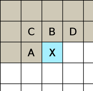
The filter function use A, B, C to predicte X.
| Type | Filter function | Predicted value |
|---|---|---|
| 0 | None | Original value |
| 1 | Sub | Byte A (to the left) |
| 2 | Up | Byte B (above) |
| 3 | Average | Mean of bytes A and B, rounded down |
| 4 | Paeth | A, B, or C, whichever is closest to p = A + B − C |
The filter function 0 means the data is original value. So we can decode previous scanline bits to scanline pixel indexes.
Scanline Pixel Indexes
| Rows | Pixel index | Pixel index | Fill… |
|---|---|---|---|
0 |
00 |
01 |
0000 |
1 |
10 |
11 |
0000 |
With previouly decoded pallette [[255, 0, 0, 255], [0, 255, 0, 255], [0, 0, 255, 255], [255, 255, 255, 127]].
Scanline Pixels
| Rows\Columns | 0 |
1 |
|---|---|---|
0 |
(255, 0, 0, 255) |
(0, 255, 0, 255) |
1 |
(0, 0, 255, 255) |
(255, 255, 255, 127) |
Chunk End 6
| 127 ~ 130 |
|---|
39, 168, 232, 87 |
Check CRC32.
Chunk Begin 7
| 131 ~ 134 | 135 ~ 138 |
|---|---|
0, 0, 0, 0 |
73, 69, 78, 68 |
0 |
IEND |
0 byte IEND critical chunk.
Chunk Data 7 IEND
No data.
Chunk End 7
| 139 ~ 142 |
|---|
174, 66, 96, 130 |
Check CRC32.
So the output ImageData is:
ImageData
imageData = {
  width: 2,
  height: 2,
  data: [255, 0, 0, 255, 0, 255, 0, 255, 0, 0, 255, 255, 255, 255, 255, 127],
};
Conclusion
We have successfully decoded the PNG image from raw binary data to ImageData. But we have ignored a lot side logics and details. Some are listed below:
IDATchunk can be split into multiple chunks. So when we should wait till we meetIENDchunk before we decode theIDATchunk.- There are 4 kinds of critical chunk and 14 kinds of ancillary chunk. See Summary of standard chunks in PNG Specification.
- Interlacd PNG are encoded in a way that the users feel the the image is loaded faster. But it gives the larger
IDATchunks.
You can get the source code on GitHub.